Continutiy of the Weathered Exterior Envelope- Can it be Realistically Achieved?

By: Mitzi Roadcap Senior Consultant, Curtainwall Design & Consulting, Inc.
The majority of those in the construction industry have sat through at least one presentation or read at least one article that discusses the issue of how to build a more energy efficient building; how to manage condensation and water infiltration; how to enhance thermal performance of the exterior envelope without creating condensation issues; or how to build “green buildings.” One important method utilized in achieving enhanced building performance is to provide continuity between the systems that comprise the weathered exterior envelope.

The weathered exterior envelope includes all of the assemblies that are used on the exterior of a building’s structure to isolate the interior from the exterior. This includes the roof assembly, the exterior wall assembly and the below-grade assembly whether it is a waterproofing or dampproofing system. Beyond aesthetics, the sole purpose of each of these assemblies is to protect the building & structural members, interior finishes and the conditioned interior space from the detrimental effects of the exterior environment. The assemblies must control air infiltration and exfiltration, control moisture migration in both liquid and vapor form, provide thermal isolation between the conditioned interior space and the exterior climate and use individual components that will not adversely affect the indoor air quality or have a detrimental affect on the environment. They must also accommodate all imposed structural movements transferred into the systems from the building’s structure in addition to their individual component thermal movements, fabrication and construction tolerances from adjacent systems as well as individual component tolerances within the assembly, imposed deadload and windload forces, and (depending upon the building’s end use and location) seismic, impact and blast loads.
Failure to fully design the transition between the exterior envelope assemblies prior to field installation quite often leads to improperly installed materials or incompatible materials coming into direct contact with one another leading to failure of one or both of the components. This in turn leads to water infiltration issues on the interior, uncontrolled air flow and decreased thermal performance of the exterior envelope. The type of materials used in each assembly will affect the means and methods used to complete the transition as well as the installation sequencing, so the design of the assembly transitions should be project specific based upon the individual products used in the application.
For the sake of brevity, assume that the design team consisting of the architect, the structural engineer, and their assorted consultants have done their job in the initial design stages so that the exterior envelope systems depicted within the architectural drawings and specified in the project documents meet the overall building performance requirements for air, water, thermal and structural integrity. Let’s also assume they meet the building a nd energy code requirements and will complement and enhance the HVAC system design to reduce energy costs. Obviously, if issues are discovered with the document details or specified products, then they should be brought to the attention of the design team as soon as possible for a quick resolution.
If we acknowledge that providing continuity between the exterior envelope assemblies is good construction practice and that it will improve the overall performance of the building, then the question becomes, “How do we realistically achieve this continuity?” The short answer is a massive coordination effort between all involved trades and members of the design team ending with working details. The details should clearly define and depict all materials used in the transition and in the proper installation sequence.
A general checklist for the process would be:
- Choose the individual components of each exterior envelope assembly that is to be used on the project. Once the manufacturer and the material are chosen then it can be determined how the membranes will be married together to achieve continuity.
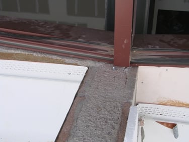
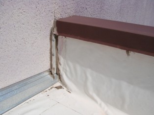
- Define all of the different conditions that exist on the project so a detail can be generated for each condition. Pay particular attention to changes in plane where a low roof parapet terminates into the face of a return exterior wall; inside and outside corners; plaza deck waterproofing and roof membrane transitions into the sill of an exterior wall; and glazed curtain wall parapets. Keep in mind that the water-resistant barrier on the roof must marry into the water-resistant barrier of the opaque exterior wall which must marry into the water-resistant barrier of the below-grade waterproofing or dampproofing to achieve continuity. The laps of the various barriers must be in a shingle type fashion in the direction of drainage, starting with the roof over the exterior wall and the exterior wall over the below-grade. Additionally, an air and water tight weathered surface compatible with the weather sealant should be provided adjacent to the glazed fenestration systems for the primary weather seal. The adjacent water-resistant barrier must integrate with the weathered surface to provide the continuity between the exterior wall assemblies.
- It is important that all team members responsible for the installation of the water-resistant barrier at the exterior opaque wall, roof, below-grade system and plaza decks (if applicable) should have a general understanding of how each of the exterior wall components will function. Where is the water-resistant barrier located for each system? Is the exterior wall system a cavity wall, a barrier wall or a wall with a hidden drainage plane? How does the system drain accumulated water? Where is the primary weather seal located? These are just a few of the questions that need to be addressed.
- Termination of the water-resistant barrier behind opaque exterior wall elements at openings is a special condition which should be addressed once the type of glazed fenestration wall is established. This is particularly important when the opening is adjacent to a wet cavity wall construction as both water and air in the cavity wall must be isolated from and prevented from entering the opening.
- Discuss installation schedules of the various exterior envelope systems so the sequencing of the materials involved in developing the transition details can be properly installed in the correct manner. This may require some tweaking of the installation schedule, so be flexible.
- involved parties sit down together and work through each of the details so that the assembly transitions work for all scopes.
So the answer to the question, Can we realistically achieve continuity of the exterior weathered envelope,” is, yes, we can as long as all involved parties are willing to work together to achieve the final goal. While each individual element used in the exterior envelope assembly may be provided and installed by a different party, all of the elements must work together as a whole at the end of the day to produce an exterior weathered envelope that will provide the owner with successful long-term performance. Upfront cooperation between the interested parties prior to construction and follow through during construction definitely contributes to the success of achieving this goal.
Ms. Roadcap started in the construction industry in 1980 and has been with CDC, Inc. since 1982, starting in the Production/Engineering Department and moving into the Consulting Department in 1997. She is a Senior Consultant and has worked on low-rise to monumental high-rise projects across the United States, the Pacific Rim and Europe. Her primary responsibilities include working with the Design Team on new construction projects from the Schematic Design through the Construction Administration phase. Her particular expertise is focused on the exterior wall elements which include both fenestration systems and opaque wall systems. She can be reached at 972-437-4200 or email to mroadcap@cdc-usa.com.
Subscribe Today!
Stay-in-the-know and subscribe to our blog today!