Building Envelope Air Barrier Continuity
By: Michael S. Plewacki; MBA, LEED AP, BD+C, CEI, RRO
Sr. Consultant/Manager Texas & Southwest Region
Morrison Hershfield
Preface
Texas has always embraced a spirit of independence and has been blessed with abundant resources. We as a community are keenly aware that preserving our resources is the right thing to do and have embraced sustainable practices in construction as an industry.
The US Department of Energy has estimated that buildings consume 40% of our nation’s primary energy. Concern raised by such figures has resulted in upcoming changes to building codes and LEED version 4, which is making it more important than ever for us as owners, architects, builders and consultants to be aware of how our building envelope performs – not only in terms of weather resistance but also in terms of air infiltration and energy performance.
The Evolution of Air Barriers
The concept of energy efficient building envelope design is not new. During the energy crisis of the 1970s engineers and researchers were tasked with devising ways to improve energy performance characteristics of buildings. This research lead to the concept of high performance wall assembly designs to separate the interior and exterior environmental conditions through the use of an air barrier to prevent the uncontrolled mixing of the air on either side of the assembly.
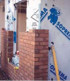 Although it may appear to be a recent phenomenon, the air barrier concept has been in use throughout the United States for the better part of three decades and modern practices are increasingly embracing this concept of a passive and hidden air barrier to discretely achieve high performance building envelope design.
Differentiating Air Barriers and Vapor Retarders
Although their names are sometimes interchanged, air barriers should not be confused with vapor retarders. A difference in air pressure across the envelope is what drives the movement of air. Typically, this pressure difference is attributed to one of three mechanisms: direct external forces such as wind; a chimney or stack effect caused by warm air rising; or internal mechanically induced air pressures. The fluid properties of the air are what demand that a continuous barrier impermeable to air be used to prevent uncontrolled infiltration and exfiltration.
Vapor retarders, on the other hand, are membranes that are used to impede the diffusion of water vapor across the surface to a rate where it can be considered negligible. Water vapor is a specific gas in the air mixture. It has a separate pressure (vapor pressure) that changes relative to the moisture content in the air.
To visualize this principle of vapor pressure, imagine a sealed box. The air inside the box has the same temperature as the exterior air and they both are at the same atmospheric air pressure. The only difference is that the relative humidity of the air inside the box is at 30% and the air outside of the box is at 80%.
In this example there is no pressure differential across the envelope of the box, thus no drive for air movement. There is however, a large vapor drive. The vapor exterior of the box is driven to diffuse to the interior where the vapor pressure is less. In this way, the pressure of the water vapor within the air mixture is separate from the pressure of the air mixture itself.
Because the driving mechanisms of each are independent, it is possible to have an air barrier that is fairly vapor permeable. It is also possible for a vapor retarder to be air tight and act as an air barrier.
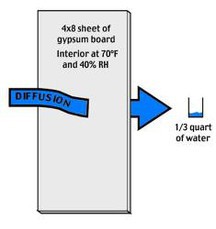
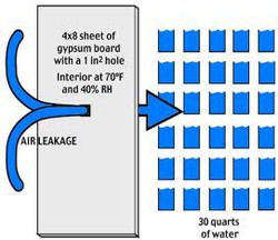
In designing and implementing an air barrier / vapor retarding system it is important to understand that air movement is by far more capable of transferring moisture across a wall section than vapor drive alone.
Energy Savings and Air Barriers
The illustration above based on Department of Energy research shows just how much more capable air movement can be in transferring moisture. The example shown is for a 1 square inch hole. It doesn’t take much imagination to visualize the consequence from multiple areas of air barrier discontinuity, punctures or failed sealant joints.
To put this into perspective of energy, let’s use an example of a rectangular high-rise commercial building (12 floors, 500,000 sq. ft.). Reducing leakage from a high infiltration rate (1.55 cfm/sq. ft. of envelope area) to a low air infiltration rate (0.4 cfm/sq. ft. of envelope area) represents an energy savings of 5% in Houston, Texas.
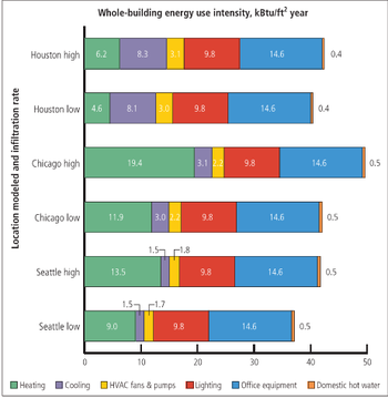 While this figure may not seem overly impressive it should be considering that Houston is a cooling dominated climate. More heating energy is needed to make up for cold air infiltration. In a cold climate such as Chicago, the energy savings using the same model above would be closer to 15%. However, a savings of 5% in Houston is still quite significant when you take into consideration rising costs of energy over the lifecycle of a building.
Keys to Project Success
Without an understanding of the design concept and communication to the construction team, trades will often build using typical weather barrier details designed to prevent water penetration. While details are often appropriate for the prevention of water ingress they are generally inadequate when the weather barrier is also used to achieve a continuous air barrier membrane. With more and more projects using sheet or fluid applied air and water barriers in cavity wall or rain screen construction, special attention needs to be paid to interfaces and penetrations to ensure continuity of seals. During drawing/document reviews or installation reviews we find this continuity lacking. On more than one occasion we have seen specifications call for the continuity, but drawings don’t show it. While it’s arguable that the contractor should have read and interpreted the specification, this sort of inconsistency only exacerbates problems in the field and stands in the way of achieving the goals of the project.
Design and Implementation: Detailing of the air barrier is critical to achieving continuity, especially at interface details such as walls to roof, through-wall flashings, windows and foundations.
Even a small discontinuity in the air barrier can result in significant air leakage and greatly reduce the effectiveness of the air barrier system. In most cases, air barrier failures are a result of inadequate detailing, or in the case of existing aging buildings, material failures due to reaching the end of their serviceable life.
With new construction it is critical that the design concepts and details are well developed and that they are clearly communicated to the construction team. To ensure overall project performance, the air barrier should be part of project commissioning as would any other significant system of the building.
Commissioning: Building commissioning for the exterior envelope is a quality focused process to ensure that the owner’s project requirements are met throughout design and construction. In the design phase, some aspects of commissioning the air barrier systems should include selecting the appropriate air barriers for permeability and detailing continuity of air barriers across joints and envelope systems.
In the process of envelope commissioning, it is critical to include coordination with significant team members and disciplines such as the structural engineer to ensure selected air barriers can accommodate expected movement at interface and structural connections, MEP to ensure HVAC systems are designed for expected infiltration, and energy consultant to ensure that the modeling for energy goals uses appropriate values for infiltration.
In the construction phase, air barrier performance testing, mock-ups, benchmarking and monitoring of the field application should all be part of the commissioning process to precede other more involved testing such as whole-building air infiltration testing following project completion.
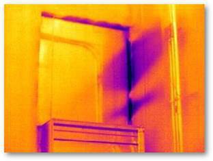 Validation: Post construction and existing building air barrier performance and continuity can be studied using infrared thermagraphic imagery as a diagnostic tool to identify and locate issues.
With recent advances in technology, tools such as whole-building air infiltration testing, and thermagraphic imagery can be combined to provide an overall project air-infiltration metric along with pin-point isolation of problems by scanning entire elevations of a building with sub degree accuracy readings from the imagery system.
Existing buildings can take advantage of this same technology in helping to isolate air leakage from failed aged materials where previously a hands-on inspection would be required.
Synopsis
From proper detailing to material selection and construction quality control and commissioning, several factors contribute to the effectiveness of an air barrier and its ability to reduce energy consumption. The concept is not new or complicated but it does require a commitment by all parties involved in the design and construction process. Individuals participating in energy efficient building teams should not only understand their specific area of expertise, but how their work influences the overall project and have a working knowledge of the role of the other disciplines involved. This is just true whether you are a consultant, design professional or contractor.
The significance of effective air barrier performance is something that cannot afford to be overlooked. While energy may be the staple of our economy in Texas, it’s not something any of us want to waste.
For more information on air barriers I encourage you to visit the Air Barrier Association of America (ABAA) website (www.airbarrier.org). This organization has a wealth of information and training resources for both design professionals and contractors.

Michael Plewacki joined Morrison Hershfield in 2014 as Regional Manager for the Texas / Southwest US Building Consultation Group and Sr. Building Envelope Consultant. Morrison Hershfield provides integrated solutions to residential, institutional, industrial and commercial clients who require reliable and cost effective systems in both new and retrofit facilities. The combined skills of our engineers, architects, technicians and support personnel with their diverse backgrounds in design and construction provide clients with a team recognized as leaders in the field of building science. MH has 17 offices across North America and over 900 employees including 160 building envelope specialists. Michael can be reached at 832-840-3083 or mplewacki@morrisonhershfield.com
Subscribe Today!
Stay-in-the-know and subscribe to our blog today!
